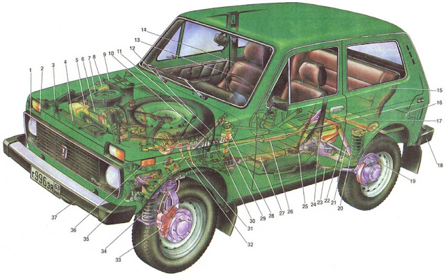
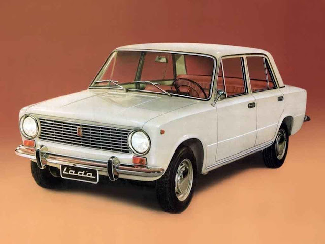
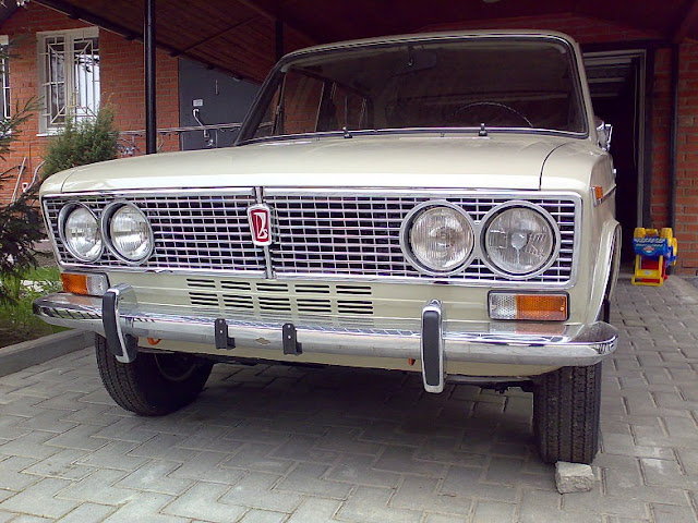
Fig. 1. The device of cars. 1. Headlight; 2. Front light; 3. The jack; 4. Radiator; 5. A tank of washers of a windshield and headlights; 6. The engine; 7. Air filter; 8. The expansion tank of the cooling system; 9. The rechargeable battery; 10. The differential lock lever in the transfer case; 11. The gear shift lever; 12. The gear lever in the transfer case; 13. steering wheel; 14. The front seat; 15. The back seat; 16. A tank of a washer of back glass; 17. The main muffler; 18. The rear bumper; 19. The rear brake; 20. Spring rear suspension; 21. The rear shock absorber; 22. The transverse reaction rod of the rear suspension; 23. The longitudinal reaction rod of the rear suspension; 24. fuel tank; 25. The rear axle; 26. Additional silencer; 27. Rear propeller shaft; 28. A tank for a liquid of a hydraulic actuator of brakes; 29. A tank for a hydraulic fluid clutch; 30. Transfer case; 31. Clutch pedal; 32, brake pedal; 33. front brake; 34. Spring front suspension; 35. Front axle; 36. Side direction indicator; 37. The front bumper.
VAZ-21213 and VAZ-21214 cars are comfortable, high-speed, compact, all-wheel drive all-wheel drive cars designed for the transport of passengers and goods on roads with all kinds of coatings and dirt roads. Cars combine the high cross-country ability of an all-terrain vehicle with all-wheel drive with the conveniences, comfort, dynamics and high-speed qualities of a modern passenger car.
The engine, clutch housing and gearbox are interconnected and form a power unit, which is mounted on the car at three points on rubber cushions.
The engine is a four-stroke, carbureted, in-line, with an upper camshaft. Compared to the VAZ-2121, engine power is increased, making it better able to adapt to load changes.
Engine lubrication system - with full-flow oil filter.
Cooling system - liquid, closed type. The system includes a body heater, which receives fluid from the cylinder head and is discharged to the pump. Coolant is special with a low freezing point and a high boiling point. The radiator is aluminum with the best heat transfer characteristic and more technological than the brass radiator of the VAZ-2121.
The power system includes an air filter, a fuel tank, a fuel pump and a carburetor. The fuel tank is located under the rear seat. The carburetor is equipped with a high-efficiency dry-type air filter with a paper filter element.
The Solex carburetor is installed, similar to that used on VAZ 2108 - 2109. Such a carburetor in combination with a contactless ignition system provides a reduction in fuel consumption.
Transmission. Clutch - single-disk, dry with a diaphragm pressure spring and hydraulic shut-off drive. Gearbox - mechanical, three-way, five-speed. Transfer case - two-stage three-shaft with interaxle locked conic two-satellite differential.
The intermediate driveshaft connecting the gearbox to the transfer case has an elastic coupling and a universal joint of equal angular speeds. Cardan shafts of the rear and front axles at the ends with cardan joints on needle bearings with oil lubricants transmit torque from the transfer case to the main gears of the axles.
The main gears of the front and rear axles consist of a pair of bevel gears with spiral teeth of hypoid gearing. Differentials are conical two-satellite.
The front wheel suspension is independent, lever-spring, with coil coil springs, telescopic hydraulic shock absorbers and anti-roll bar.
The rear wheel suspension is a rigid beam connected to the body of one transverse and four longitudinal rods, with coil springs and with hydraulic telescopic shock absorbers.
Steering - a worm gear and a three-link steering gear with one middle and two side rods.
The brakes. Front - disc with a movable caliper. Back - drum with self-centering pads and pressure regulator. The service brake drive is hydraulic foot, with a vacuum booster, double-circuit. Parking brake - manual with cable drive to the rear brake pads.
The electric equipment of cars is made according to a single-wire circuit, in which the negative conclusions of the sources and consumers of electricity are connected to the "mass", which acts as a second wire. The current sources in the system are an alternating current generator with a built-in semiconductor rectifier and a microelectronic voltage regulator and a lead battery type 6ST-55. To start the engine, a starter 35.3708 is used.
Car body - supporting structure, three-door, all-metal. The body is a welded structure assembled from panels, side members, crossbars, struts and various amplifiers.
The side doors with the front hinge have two safety glass: the front - pivoting with a handle and a latch, the rear - lowering with a drive from the power window handle. The tailgate is hung on the body on two hinges and is locked with a lock. In the open position, the door is held by gas-filled stops. The threshold of the rear door is lowered to the level of the bumpers, which facilitates the loading and unloading of goods.
Wind and rear windows with panoramic windows. Wind - polished, three-layer, and the rear and side - hardened.
The front seats are separate with folding backs and with a mechanism for adjusting the position of the seat and the backrest. The rear seat is a common folding for the formation of a cargo area.
The VAZ-21214 car differs from the VAZ-21213 in the installation of an engine with a fuel injection system. This system meets US 1983 emission standards and improves driving performance. Changes in the engine relate to the power system, ignition and exhaust. Features of the fuel injection system are shown in Fig. 33 and 34.
Technical characteristics of cars VAZ-21213, 21214
Number of seats, including driver's seat 4
Load capacity kg 400
The mass of the equipped car, kg 1210
Base (distance between axles), mm 2200
Wheel track, mm:
front 1430
rear 1400
Vehicle clearance at full load and normal tire pressure, mm:
to the cross member of the front suspension 288
to the rear axle beam 220
to crankcase 319
Overall dimensions, mm:
length 3740
width 1680
height (no load) 1640
Maximum speed in high gear, km / h:
at full mass of the car 135
with driver and one passenger 137
Car acceleration time from standstill with gear shifting to a speed of 100 km / h:
at full mass of the car 21 second
with driver and one passenger 19 second
The smallest turning radius along the axis of the track of the front outer wheel, m: 5.5
The braking distance of a car with a full load at a speed of 80 km / h on a horizontal section of a dry, flat asphalt highway, m 40
Engine model 21213, 21214 *
Bore and stroke, mm 82x82
Working volume, litre 1.7
Compression ratio 9.3
Rated power according to GOST 14846 (net) at a crankshaft rotation speed of 5200 (5400 *) rpm, hp 78.9
Gear Ratios:
first 3.67
second 2.1
the third 1.36
the fourth 1.00
fifth 0.82
reverse 3.53
Final drive ratio (both axles) 3.9
Transfer Case Ratios:
top gear 1,2
low gear 2,135
Wheel rim size 127J-406 (5J-16)
Tires
diagonal 175-406 (6.95-16) or radial 175 / 80R16
* For the car VAZ-21214
Engine
 |
Engine Niva
|
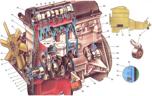
Fig. 2. Engine (longitudinal section). 1. Crankshaft; 2. The liner of the crankshaft main bearing; 3. Asterisk of a cranked shaft; 4. The front crankshaft oil seal; 5. Crankshaft pulley; 6. Ratchet; 7. The cover of the drive of the gas distribution mechanism; 8. A belt of a drive of the pump of a cooling liquid and the generator; 9. The pulley of the generator; 10. Asterisk of the drive of the oil pump, fuel pump and ignition distributor; 11. The roller drive the oil pump, fuel pump and distributor; 12. Cooling fan; 13. The cylinder block; 14. The cylinder head; 15. The timing chain; 16. Camshaft sprocket; 17. exhaust valve; 18. Inlet valve; 19. Housing for camshaft bearings; 20. Camshaft; 21. The lever of the valve drive; 22. Cylinder head cover; 23. Sensor, coolant temperature gauge; 24. Spark plug; 25. Piston; 26. Piston pin; 27. Holder of a back epiploon of a cranked shaft; 28. Thrust half ring of a crankshaft; 29. Flywheel; 30. The upper compression ring; 31. Lower compression ring; 32. Oil scraper ring; 33. The front cover of the clutch housing; 34. oil pan; 35. Front support of the power unit; 36. Connecting rod; 37. Bracket of the front support; 38. Powertrain; 39. The rear support of the power unit.
The layout of the engine is simple and compact. All engine components that require adjustment and maintenance are located in easily accessible places.
Cylinder block. Block 13 is cast from special cast iron. The cylinders of the block are divided in diameter through 0.01 mm into five classes, denoted by the letters A, B, C, D, E. The cylinder class is indicated on the lower plane of the block against each cylinder. The cylinder and the piston mating with it must be of the same class to provide a clearance between the piston and the cylinder of 0.05-0.07 mm. The diameters of the cylinders of each class are as follows, mm:
Class Bore
A 82,000-82,010
B 82.010-82.020
C 82,020-82,030
D 82,030-82,040
E 82,040-82,050
Five bearings of the crankshaft main bearings with thin-walled steel-aluminum inserts are located in the lower part of the cylinder block. The holes for the crankshaft bearings in the cylinder block are machined complete with covers. Therefore, bearing caps are not interchangeable, and risks have been made to distinguish on their outer surface.
In the rear support there are slots for installing persistent half rings 28 that hold the crankshaft from axial movements. A steel-aluminum half-ring is installed on the front, and a metal-ceramic (yellow) impregnated with oil on the back. The value of the axial clearance of the crankshaft during engine assembly is provided in the range of 0.06-0.2 mm. If in operation the gap exceeds the maximum permissible (0.35 mm), it is necessary to replace the persistent half rings with new or repair ones, increased by 0.127 mm. Grooves located on one side of the half rings should face the thrust surfaces of the crankshaft.
In the front of the cylinder block there is a cavity for the timing mechanism, closed by a cover 7. On the rear side of the cylinder block is attached a holder 27 of the rear oil seal. Self-clamping seals are installed in cover 7 and holder 27. On the left side of the block there is a roller 11 of the drive of auxiliary units. Steel-aluminum bushings are pressed into the holes for the roller bearings.
The cylinder head 14 is common to four cylinders, cast from an aluminum alloy. Cast iron seats and valve guides are pressed into the head. Spiral grooves for lubrication are cut in the holes of the guide bushes. To reduce the penetration of oil into the combustion chamber through the gaps between the sleeve and the valve stem, metal-rubber oil reflector caps are used.
The cylinder head is attached to the cylinder block by eleven bolts. Between the head and the cylinder block there is a gasket made of asbestos material on a metal frame and impregnated with graphite.
Pistons 5 are made of alumi
num alloy. The piston skirt is oval in cross section and has a conical shape in height. In addition, a steel thermocompensating steel plate is embedded in the piston heads. All this is done to compensate for the non-uniform thermal deformation of the piston during heating. The piston bosses have openings for the passage of oil to the piston ring.
The hole for the piston pin is offset from the axis of symmetry by 1.2 mm to the right side of the engine to reduce the knock of the piston when passing through the TDC. Therefore, the arrow is branded on the piston bottom, which must be turned towards the front of the engine during assembly.
Pistons, like cylinders, are sorted by five outer diameters by 0.01 mm and by the diameter of the piston pin bore by three diameters by 0.004 mm, indicated by numbers 1, 2, 3. Piston class (letter) and hole category under the piston pin (number) are branded on the piston bottom. During manufacture, the mass of pistons is strictly maintained. Therefore, when assembling the engine, it is not necessary to select the pistons of one group by weight.
Piston pin 6 - steel, cemented, tubular section, floating type, i.e., freely rotates in the piston bosses and the connecting rod sleeve. The finger is fixed in the piston with two steel snap rings. Piston fingers, like holes in piston bosses, are divided into three categories according to their outer diameter after 0.004 mm. The category of the finger is marked on its end with color: blue - the first category, green - the second, red - the third. The assembled pin and piston must belong to the same category.
Piston rings 30, 31 and 32 are made of cast iron. The outer surface of the upper compression ring 30 is chrome-plated to increase wear resistance and has a barrel-shaped generatrix to improve workability. The lower compression ring 31 is scraper type (with a groove on the outer surface), phosphated. The ring must be installed with the groove down. The oil scraper ring 32 has slots for the oil removed from the cylinder and an internal coil spring (expander).
The connecting rods 36 are steel, forged, with a split lower head, in which the connecting rod bearing shells are installed. The connecting rod is processed together with the cover, so when assembling the numbers on the connecting rod and cover must be the same.
A steel-bronze bushing is pressed into the upper head of the connecting rod. According to the diameter of the hole of this sleeve, the connecting rods are divided into three classes through 0.004 mm, like the pistons. The class number is branded on the top head of the connecting rod.
By weight of the upper and lower heads of the connecting rods are divided into classes marked with paint on the connecting rod rod. Cranks of the same class by weight should be installed on the engine, i.e. with the same marking.
The connecting rod bolts are pressed into the lower connecting rod head. Therefore, in order not to disturb the seating of the bolts in the holes of the head, it is impossible to extrude the bolts from the connecting rod head during repair work.
Crankshaft 1 - five-bearing, cast from cast iron. The shaft necks are hardened by high-frequency currents to a depth of 2-3 mm. At the rear end of the crankshaft, a socket is made for the front bearing of the input shaft of the gearbox, the flywheel 29 is centered on the outer diameter of the flywheel. and on one side of the crankshaft axis.
Inserts of main and connecting rod bearings - thin-walled, steel-aluminum. All connecting rod bearings are the same and interchangeable. The upper liners of the 1st, 2nd, 4th and 5th main bearings are the same, with a groove on the inner surface, and the lower ones without a groove. The liners of the 3rd main bearing differ from the others in the larger width and the absence of grooves on the inner surface.
 |
engine cross section
|
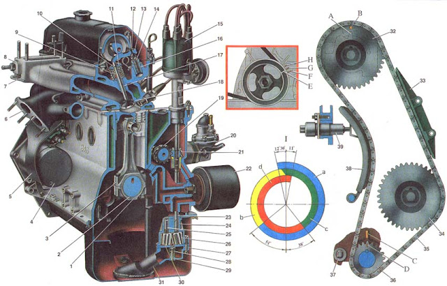
Fig. 3. Engine (cross section). 1. Connecting rod cover; 2. Connecting rod insert; 3. Connecting rod; 4. Starter; 5. The heat-insulating shield of a starter; 6. exhaust manifold; 7. Inlet pipe drain pipe; 8. Inlet pipe; 9. Oil reflection cap; 10. Cracker valve; 11. Plate of springs; 12. The spring of the valve actuator lever; 13. The lever of the valve drive; 14. Valve adjustment bolt; 15. Distributor of ignition; 16. Bush adjusting bolt; 17. Valve guide bush; 18. Valve seat; 19. Roller drive oil pump, fuel pump and distributor; 20. The fuel pump; 21. Gear drive oil pump, fuel pump and distributor; 22. oil filter; 23. The roller of the oil pump; 24. Oil pump housing; 25. The axis of the driven gear oil pump; 26. Pinion gear of oil pump; 27. The cover of the oil pump; 28. Spring pressure reducing valve; 29. The pressure reducing valve of the oil pump; 30. Driven gear oil pump; 31. A reception branch pipe of the oil pump; 32. Camshaft sprocket; 33. Chain caliper; 34. Asterisk of an oil pump drive, ignition distributor sensor and fuel pump; 35. The timing chain; 36. Asterisk of a cranked shaft; 37. The restrictive finger of the chain; 38. Shoe tensioner; 39. Tensioner; A. Mounting protrusion on the camshaft bearing housing; B. Positioning mark on camshaft sprocket; C. Installation mark on the cylinder block; D. Alignment mark on crankshaft sprocket; E. TDC mark on the crankshaft pulley; F. Ignition timing mark 0 °; G. Ignition timing mark 5 '; H. 10 ° ignition timing mark; I. Diaphragm of the phases of the gas distributor: a - intake of the combustible mixture; b - compression; C is the working stroke; d - issue.
The gas distribution mechanism ensures that the engine cylinders are filled with a combustible mixture and the exhaust gas is released in accordance with the cylinder operating procedure and the gas distribution phases adopted for the engine. The details of the mechanism include: camshaft, valves and guide bushings, springs with fasteners, valve levers.
Camshaft controlling the opening and closing of valves, cast iron, cast. The friction surfaces of the cams are bleached. This process consists in electric arc melting of surfaces, as a result of which a layer of so-called "white" cast iron is formed, which has high hardness. The shaft rotates on five bearings in a special housing 19 (see Fig. 2), and is kept from axial movements by a stop flange placed in the groove of the front shaft journal.
Valves (intake and exhaust) are located in the cylinder head obliquely in one row. The inlet valve head has a larger diameter for better filling of the cylinder, and the working facet of the exhaust valve, operating at high temperatures in an aggressive exhaust gas environment, has a heat-resistant alloy overlay. Springs press the valve to the seat and do not allow it to come off the actuator lever. The upper support plate 11 of the springs is held on the valve stem by two crackers 10, which are folded in the shape of a truncated cone.
The levers 13 transmit force from the camshaft cam to the valve. The lever at one end rests on the spherical head of the adjusting bolt 14, and the other on the valve end. The adjusting bolt is screwed into the sleeve 16 and locked with a lock nut.
Drive auxiliary units. Auxiliary engine assemblies and a gas distribution mechanism are driven from the crankshaft by a chain drive. It consists of a two-row sleeve-roller chain 5, a drive sprocket 36 on the crankshaft, a driven sprocket 4 for auxiliary drive units, a driven sprocket 2 for a camshaft, a chain damper 35 and a tensioner 39 with a shoe 38. The tensioner shoe and the chain stabilizer have a steel frame with a vulcanized rubber layer .
A restrictive pin 37 is wrapped around the crankshaft sprocket in the cylinder block. It prevents the chain from falling into the crankcase when removing the camshaft sprocket (when the cylinder head is removed on the car).
When loosening the tensioner fixing nut, the chain is pulled by a shoe 38, on which the tensioner springs act. The tensioner shoe rotates around the mounting bolt. After tightening the nut 46, the rod 44 is clamped with the collets of the cracker 45, as a result of which the spring 43 of the chain tensioner is blocked. When the engine is running, only the inner spring 47 acts on the plunger 49, which ensures, through a clearance of 0.2-0.5 mm, in the tensioner mechanism, compensation of the chain oscillations. The circuit breaker 3 dampens the vibrations of the leading branch of the chain. When the engine is running, the chain is pulled. It is considered operable if the tensioner provides tension, i.e. if the chain is stretched no more than 4 mm.
The roller 19 of the drive of the oil pump, the ignition distribution sensor and the fuel pump is installed along the engine and has two support necks, a helical gear and an eccentric, which drives the fuel pump through the pusher. The helical gear of the roller 19 is engaged with the gear 21, which drives the ignition distribution sensor and the oil pump. Gear 21 rotates in a cermet sleeve, pressed into the cylinder block. An aperture with slots is made in the gear, into which the spline ends of the rollers of the ignition distribution sensor and oil pump enter.
Engine operation. For one working cycle, four cycles occur in the engine cylinder - the admission of a combustible mixture, compression, stroke and exhaust gas. These measures are carried out in two revolutions of the crankshaft, i.e. each cycle occurs half a turn (180 °) of the crankshaft.
The inlet valve begins to open 12 ° 30 'before the piston approaches the top dead center (TDC). This is necessary so that the valve is fully open when the piston goes down. The valve closes 51 'after the piston passes the bottom dead center (BDC). Due to the inertial pressure of the jet of the suctioned-in combustible mixture, it continues to flow into the cylinder when the piston has already begun to move upward, and thereby provides better filling of the cylinder.
The exhaust valve begins to open 38 ° before the BDC. At this point, the pressure in the cylinder is still quite large, and the gases begin to flow out intensively from the cylinder. The valve closes 10 ° after the piston passes through the TDC.
There is such a moment (23 ° 30 'of crankshaft rotation near TDC) when both valves - inlet and outlet are open at the same time. This position is called valve closure. Due to the short period of time, valve closure does not lead to the penetration of exhaust gases into the intake pipe, but rather, the inertia of the exhaust flow causes the fuel mixture to leak into the cylinder and improves its filling.
To ensure that the valve opening and closing moments are consistent with the crankshaft rotation angles (i.e., to ensure the correct timing), the crankshaft and camshaft sprockets have marks D and B, as well as C on the cylinder block and A (protrusion) on the housing camshaft bearings. If the gas distribution phases are set correctly, then with the piston of the fourth cylinder at TDC at the end of the compression stroke, mark A should coincide with mark B and mark C with mark D. When the camshaft drive cavity is covered by a cover, the position of the crankshaft can be identified by marks on the crankshaft pulley and camshaft cover.
To ensure the correct operation of the gas distribution mechanism during thermal expansion of parts on a running engine, the clearances between the cams and the valve drive levers are set to 0.15 mm for inlet valves and 0.20 mm for exhaust valves on a cold engine. If there are more gaps, then the valves will open late and close ahead of time. If there is no clearance, the valves on a running engine will remain slightly ajar. As a result, the durability of valves and seats will be sharply reduced, engine power will drop.
Engine lubrication system
 |
Engine lubrication system
|
Fig. 4. Engine lubrication system: 1. A hole in the sprocket for chain lubrication; 2. The main channel in the camshaft; 3. The channel in a camshaft cam; 4. An annular undercut on the middle support neck of the camshaft; 5. Oil filler neck; 6. The channel in the camshaft journal; 7. Inclined channel in the cylinder head; 8. The channel for supplying oil to the gas distribution mechanism; 9. The main oil line in the cylinder block; 10. Sensor of a signal lamp of insufficient oil pressure; 11. The channel for supplying oil to the main bearing; 12. The oil supply channel to the connecting rod bearing; 13. Oil sump; 14. oil filter; 15. Bypass valve; 16. Cardboard filter element; 17. Anti-drain valve; 18. The oil pump; 19. The oil supply channel from the pump to the filter; 20. The channel for supplying oil from the filter to the main oil line; 21. The channel for supplying oil to the hub of the gear wheel drive the oil pump; 22. The front crankshaft oil seal; 23. The oil supply channel to the main bearing and to the drive shaft of the oil pump; 24. The roller drive the oil pump and distributor; 25. Inlet pipe; 26. Throttle valve of the second carburetor chamber; 27. Throttle valve of the first carburetor chamber; 28. air filter; 29. Collector for exhaust ventilation; 30. flame arrester; 31. Hose suction crankcase gases in the throttle space of the carburetor; 32. Exhaust hose; 33. Oil level indicator; 34. The cover of the oil separator; 35. oil separator; 36. drain pipe; I. Scheme of ventilation of the crankcase.
Combined lubrication system: under pressure and spray. Under pressure, the main and connecting rod bearings, camshaft bearings, bearings of the drive shaft of the oil pump and the ignition distributor, cams of the camshaft and the gear sleeve of the gear of the drive of the oil pump and ignition distributor are lubricated.
Oil flowing from the gaps and sprayed by moving parts lubricates the cylinder walls, pistons with piston rings, piston fingers in the piston bosses, the timing chain, the bearings of the valve actuators, and the valve rods in their guide bushings. Lubrication capacity 3.75 liters.
The lubrication system includes: an oil pump 18, a receiving pipe with a filter net attached to the pump casing, a full-flow oil filter mounted on the left front side of the engine, an oil pressure reducing valve integrated in the receiving pipe, an electric sensor 10 for insufficient oil pressure.
The insufficient oil pressure sensor is connected to a signal lamp on the instrument panel, which lights up when the oil pressure drops to 0.02-0.06 MPa (0.2-0.6 kgf / cm2). When the engine is running with a working lubrication system, the lamp should go out (if the engine is not overheated).
The circulation of oil during engine operation is as follows. The oil pump 18, driven by a pair of gears with spiral teeth, draws oil from the crankcase 13 through the filter mesh of the oil intake pipe and feeds it through a channel 19 to a full-flow filter. Filtered oil through channel 20 enters the main oil channel 9, passing along the block on the left side, and from there through channels 23 and 11 drilled in the cylinder block, it penetrates to the main bearings of the crankshaft and the front bearing of the roller 24 of the oil pump drive and the ignition distributor. Oil is supplied to the central camshaft support via channels 7 drilled in the cylinder block, in the head and in the camshaft bearing housing.
The oil that comes to the central camshaft support through a groove in the support neck enters the central channel of the camshaft, and from the channel through the holes in the cams and in the support necks to the cams, levers and shaft supports.
Oil from the first bearing of the roller 24 of the drive of the oil pump and the ignition distributor enters the second bearing through a channel drilled in the roller itself. Oil is supplied to the hub of the gear drive of the oil pump and the ignition distributor via a separate channel 21 from the cavity of the block in front of the oil filter. The remaining parts are lubricated by spraying and gravity.
The timing chain is lubricated with oil, which leaves the front camshaft support and the front hub of the oil pump drive and the ignition distributor, and then is sprayed through the radial channels 1 on the sprockets of these shafts.
In order to ensure the necessary oil pressure in the line during engine operation in any mode, as well as to compensate for the increased oil consumption during engine wear, the oil pump has excessive capacity.
To prevent an increase in oil pressure above the permissible level, a pressure reducing valve is installed in the system, which allows the excess oil to pass into the oil receiver.
The oil pump (see fig. 3 "Cross section of the engine") is a gear type, mounted inside the crankcase and attached to the cylinder block with two bolts. The drive gear of the pump is fixedly mounted on the roller, and the driven gear rotates freely on an axis pressed into the housing.
A pressure reducing valve is integrated into the oil intake housing. The pressure at which the pressure-reducing valve is activated is provided by a spring of the corresponding elasticity set at the factory. This pressure is not regulated.
The oil filter is screwed onto the fitting and pressed against the annular collar on the block and sealed with a gasket. The oil enters the filter through the hole and, passing the filter element 16, enters the main oil channel 9 of the block through the central hole and the mounting fitting.
The filter has an anti-drain valve 17, which prevents the oil from draining from the system when the engine is stopped, and an overflow valve 15 that is activated when the filter element is clogged.
Crankcase ventilation system. During engine operation, a certain amount of exhaust gas enters the crankcase through the gaps. For the removal of gas and gasoline vapors from the crankcase, which increases the life of the oil and increases the durability of the engine, there is forced crankcase ventilation by exhausting gases from the crankcase into the engine intake pipe.
Crankcase gases are aspirated through hoses 31 and 32 to the carburetor throttle device and to the carburetor through the exhaust manifold 29.
At a low frequency of rotation of the crankshaft, the vacuum at the inlet to the carburetor is negligible (throttle valves are closed), and the bulk of the gases are sucked off through a hose 31 into the throttle space of the carburetor.
When the throttle valve 27 is ajar or fully open, the bulk of the crankcase gases will be sucked off via a hose 32 to the exhaust manifold 29 and to the carburetor, bypassing the filter element of the air filter. At the same time, a small part of the crankcase gases will pass through the hose 31, due to the small opening of the carburetor pipe.
Engine cooling system
 |
Engine cooling system
|
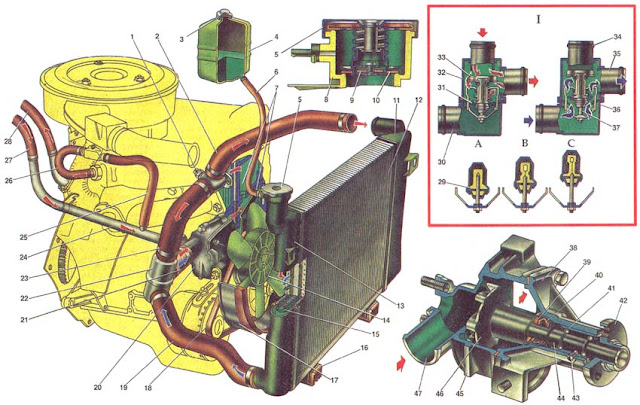
Fig. 5. The cooling system; 1. Coolant temperature sensor for fuel injection system; 2. The inlet hose of the radiator; 3. Tank cap; 4. The expansion tank; 5. Radiator plug; 6. Hose from the radiator to the expansion tank; 7. Cooling shirt; 8. filler neck; 9. Inlet valve plugs; 10. Outlet (steam) valve plugs; 11. The left tank of the radiator; 12. The core of the radiator; 13. The right tank of the radiator; 14. The impeller of the fan; 15. Turbulator; 16. Rubber radiator support; 17. Fan casing; 18. Fan belt; 19. The radiator outlet hose; 20. Coolant pump; 21. Hose for supplying coolant to the pump; 22. Thermostat; 23. Thermostat bypass hose; 24. Fluid drain pipe from the heater radiator; 25. Hose for draining fluid from the carburetor heating unit; 26. Hose for supplying fluid to the carburetor heating block; 27. Hose for draining fluid from the heater radiator; 28. Hose for supplying fluid to the heater radiator; 29. Rubber insert; 30. Inlet pipe (from radiator); 31. The main valve; 32. Thermostat housing; 33. Bypass valve; 34. A branch pipe of a bypass hose; 35. Coolant supply pipe to the pump; 36. Thermostat cover; 37. Piston; 38. pump cover; 39. Thrust sealing ring of an epiploon; 40. Oil seal; 41. The bearing of the pump roller; 42. The hub of the fan pulley; 43. Lock screw; 44. The roller of the pump; 45. pump housing; 46. Impeller of the pump; 47. A reception branch pipe; I. Thermostat operation diagram; A. The temperature of the liquid is less than 80 ° C; B. Liquid temperature from 80 to 94 ° C; C. The temperature of the liquid is more than 94 ° C.
Engine cooling system - liquid, closed, with forced circulation of coolant. The system is filled with Tosol A-40 coolant - an aqueous solution of Tosol-A antifreeze (concentrated ethylene glycol with anticorrosive and antifoam additives with a density of 1,078-1,085 g / cm3).
The cooling system is filled with 10.7 liters, including the heating system of the passenger compartment. The liquid level in the expansion tank should be 3-4 cm above the "MIN" mark, checked on a cold engine (at 15-20 ° C).
To monitor the temperature of the coolant, there is a sensor installed in the cylinder head and a pointer on the instrument panel.
The cooling system includes: a coolant pump 20, a cooling jacket for a block and a cylinder head, a thermostat 22, a fan, a radiator, an expansion tank 4, pipelines and hoses.
When the engine is running, the liquid heated in the cooling jackets enters through the exhaust pipe through hoses 2 and 23 to the radiator or thermostat, depending on the position of the thermostat valves. Next, the cooled liquid is sucked up by the pump 20 and is fed back into the cooling jackets.
The coolant pump is a centrifugal type, it is driven from the crankshaft pulley by a V-shaped generator drive belt.
The housing 45 and the cover 38 of the pump are cast from aluminum alloy. In the cover in the bearing 41, which is locked by the screw 43, a roller 44 is mounted. The bearing 41 is double-row, non-separable, without an inner race. The bearing is filled with Litol-24 grease during assembly and is not subsequently lubricated.
A cast iron impeller 46 is pressed onto the roller on one side, and a pump drive pulley hub 42 on the other. The impeller end in contact with the o-ring is hardened by high-frequency currents to a depth of 3 mm. The o-ring is pressed against the impeller by the gland spring through the rubber sleeve. The oil seal 40 is non-separable, consisting of an external brass holder, a rubber cuff and a spring. The gland is pressed into the cover 38 of the pump. The pump is driven by a V-belt 18.
The fan is a six-bladed impeller 14 made of plastic, which is bolted to the hub 42 of the pump drive pulley. The fan blades have a radius of installation that is variable in radius and a variable step along the hub to reduce noise. For better performance, the fan is located in the casing 17, which is bolted to the radiator brackets.
Radiator and expansion tank. The radiator is collapsible, with plastic tanks 11 and 13, with two rows of aluminum horizontal tubes and aluminum cooling plates. The core 12 of the radiator is sealed with tanks with rubber gaskets. For the best cooling efficiency of the liquid, turbulators are installed in the tubes 15. The radiator is mounted on rubber supports 16 and bolted to the front of the body.
The radiator filler neck is closed by a stopper 5 and connected by a hose to a translucent plastic expansion tank 4. The radiator cap has an inlet 9 and an outlet 10 (steam) valve through which the radiator is connected to the expansion tank. The inlet valve 9 is not pressed against the gasket (a gap of 0.5-1.1 mm) and allows the inlet and outlet of coolant into the expansion tank when the engine is heated and cooled.
When boiling liquid or a sharp increase in temperature due to the small flow rate, the inlet valve does not have time to release the liquid into the expansion tank and closes, disconnecting the cooling system with the expansion tank. With increasing pressure during heating to 50 kPa, the exhaust valve 10 opens, and part of the coolant is transferred to the expansion tank.
Thermostat and cooling system. The thermostat of the cooling system accelerates engine warming up and maintains the necessary thermal operation of the engine. With optimal thermal conditions, the temperature of the coolant should be in the range of 85-95 ° C. The temperature values supported by the thermostat are indicated on its bottom.
The thermostat 22 consists of a body and cover, which are rolled together with the seat of the main valve 31. The thermostat has three nozzles: an inlet pipe for coolant inlet from the radiator, a bypass hose pipe 23 for bypass fluid from the cylinder head to the thermostat, and a pipe for supplying coolant to pump 20.
The main valve 31 is mounted on a thermocouple cup in which the rubber insert 29 is rolled. The rubber insert has a polished steel piston mounted on a fixed holder. Between the walls and the rubber insert there is a heat-sensitive solid filler. The main valve 31 is pressed against the seat by a spring. Two racks are fixed on the valve, on which a bypass valve 33 is installed, which is spring-loaded.
The thermostat, depending on the temperature of the coolant, automatically turns on or off the radiator of the cooling system and passes the fluid through the radiator or bypassing it.
On a cold engine with a coolant temperature below 80 ° C, the main valve is closed, the bypass valve is open. In this case, the fluid circulates through the hose 23 through the bypass valve 33 to the pump 20, bypassing the radiator (in a small circle). This ensures a quick warm-up of the engine.
If the temperature of the liquid rises above 94 ° C, the solid thermostat filler expands, compresses the rubber insert 29 and extrudes the piston, moving the main valve 31 until it opens completely. The bypass valve 33 is completely closed. The liquid in this case circulates in a large circle: from the cooling jackets through the hose 2 to the radiator and then through the hose 19 through the main valve of the thermostat to the pump 20, which again goes to the engine cooling jackets.
Within the temperature range of 80-94 ° C, the thermostat valves are in intermediate positions, and the coolant circulates in both small and large circles. The magnitude of the opening of the main valve provides a gradual mixing of the liquid cooled in the radiator, thereby achieving the best thermal engine operation.
Supply system
 |
Supply system
|
Fig. 6. Power system; 1. The axis of the lever of mechanical pumping fuel; 2. The lever of mechanical pumping of fuel; 3. Pusher; 4. The lower case; 5. Pressure valve; 6. Discharge nozzle; 7. Suction valve; 8. Fuel filter; 9. Suction nozzle; 10. Eccentric roller drive oil pump and distributor; 11. Heat-insulating spacer; 12. Laying a heat-insulating spacer; 13. Laying the fuel pump; 14. The lever of manual pumping of fuel; 15. The balance weight; 16. Cam; 17. Pump cover; 18. Plate of diaphragms; 19. Internal thermal insulation; 20. The upper diaphragms; 21. The lower diaphragm; 22. Outer distance gasket; 23. Lever return spring; 24. The stock; 25. The upper body; 26. Carburetor; 27. fuel pump; 28. Fuel filter; 29. Check valve; 30. Fuel line fuel drain; 31. Fuel line for supplying fuel from the tank; 32. Filter intake pipe; 33. Fuel gauge sender; 34. fuel tank; 35. The separator of the vapor of gasoline; 36. Connecting hoses of a separator; 37. Air hose; 38. The filler neck; 39. A stopper of a fuel tank; 40. Ventilation hose; I. The scheme of the fuel pump; II. The scheme of installation of the fuel pump.
The power supply system of VAZ-21213 vehicles includes devices for supplying fuel and air, preparing a combustible mixture and exhaust gas. The power system consists of a fuel tank 34, a fuel pump 27, fuel lines, an air filter, a carburetor 26, silencers and pipelines. The system with the backflow of part of the fuel from the carburetor 26 through the calibrated hole of the carburetor pipe into the fuel tank. A check valve 29 is mounted on the fuel drain hose, preventing the fuel from draining from the tank through the carburetor.
Fuel tank 34 steel, stamped, welded. The capacity of the fuel tank is 45 liters, including a reserve of 4-6.5 liters.
The tank is installed inside the body under the rear seat, is separated from the passenger compartment by a special partition and is attached to the body floor with four bolts. The tank filling pipe is led into a niche located on the right side of the car and closed by a hatch. The inlet pipe is connected to the fuel tank inlet pipe with a rubber connecting hose fixed with two clamps and closed with a blind threaded plug.
The fuel tank 34 has a gas vapor separator 35, which is connected to the tank by connecting hoses 36, and connected to the atmosphere by a ventilation hose 40. Gasoline vapors, condensing in the separator, are fed back to the fuel tank.
On the flange of the upper half of the tank through the rubber gasket is attached to the sensor 33 of the fuel level indicator Assembly with a fuel receiver tube equipped with a strainer. The sensor is connected to a device mounted on the instrument panel and equipped with a red reserve lamp, which lights up when 4-6.5 liters remain in the tank. Used gasoline AI-93.
Fuel lines. Fuel from the fuel tank to the fuel pump is supplied through a steel leaded or galvanized two-layer pipeline 31. The pipeline 31 and the system instrumentation pipes are interconnected by rubber hoses in a fabric braid and secured with tie rods.
On the body, fuel pipelines are fixed with plastic holders, the holes for their passage are sealed with rubber plugs.
Fuel pump 27 - diaphragm type, with a mechanical drive; mounted on the left side of the cylinder block, mounted on two studs through a heat-insulating spacer 11 and shims 12 and 13; equipped with a lever 14 for manual pumping of fuel.
The fuel pump is driven from the eccentric 10 of the drive shaft of the oil pump and the ignition distributor through the pusher 3.
The pump consists of a lower casing 4 with drive levers, an upper casing 25 with valves and nozzles, a diaphragm assembly and a cover 17. The diaphragm assembly has three diaphragms: two upper 20 are working for supplying fuel, one lower 21 is safety, working in contact with the crankcase oil and prevents the ingress of fuel into the crankcase in case of damage to the working diaphragms. Between the working and safety diaphragms, remote outer 22 and inner 19 gaskets are installed. The outer gasket has a hole for the fuel to exit when the diaphragms are damaged. Diaphragms with plates and with an internal spacer 19 are mounted on the rod 24 and secured with a nut on top. A diaphragm assembly is installed between the upper and lower pump housings and is secured with screws. A compressed spring is mounted on the stem under the diaphragm assembly. The rod 24 with a T-shaped shank is inserted into the slot of the balancer 15. This design allows, without disassembling the diaphragm assembly, to remove it from the pump.
In the lower case 4, on the axis 1, a lever 2 for mechanical pumping of fuel and a balancer 15 are installed. In the lower case, also on an axis with a cam 16, a lever 14 for manual pumping of fuel is installed, which, under the action of the spring 23, returns to its original position.
In the upper casing 25 of the pump there are installed textolite hexagonal suction 7 and discharge 5 valves. Valves are spring-loaded to brass seats. A cover 17 is fastened to the housing from above with a central bolt. A plastic strainer 8 is installed between the cover and the housing. Suction 9 and discharge 6 nozzles are pressed into the upper housing.
When the engine is running, the eccentric 10 of the drive roller through the pusher 3 acts on the lever 2 and rotates the balancer 15, which pulls the diaphragm of the pump down through the rod 24. In this case, the spring of the diaphragms is even more compressed, a vacuum is created, as a result of which the fuel fills the working cavity through the suction valve (the cavity under the diaphragms). When the clown escapes from the pusher, lever 2, balancer 15 and rod 24 with diaphragms are released. The diaphragms under the action of a compressed spring create fuel pressure in the working cavity, the suction valve 7 is closed, and fuel is supplied through the discharge valve 5 to the carburetor float chamber.
With low fuel consumption, the diaphragm stroke will be incomplete; while the stroke of the lever 2 will partially be idle.
When manually pumping fuel, press the lever 14, the cam 16 is turned, which acts on the balancer 15 and pulls the rod 24 with diaphragms. The fuel is sucked into the working cavity. When you release the lever 14, the cam under the action of the spring 23 returns to its original position, and the diaphragms pump fuel into the carburetor.
Gaskets are made of three types and have a thickness of 0.30; 0.75 and 1.25 mm. An adjustment gasket with a thickness of 0.30 mm must always be placed between the heat-insulating spacer and the cylinder block.
Fine fuel filter. In front of the fuel pump 27, a fine filter is installed on the rubber hoses and mounted on the hoses with tie rods. The filter is non-separable design, with a paper filter element in a plastic case, the case with a cover are welded by ultrasonic welding or high frequency currents. The fineness of the filter element is up to 15 microns. For proper installation of the filter on the hoses, an arrow is marked on the body of the fuel through the filter.
Carburetor
 |
| Carburetor |
Fig. 7. Carburetor model 21073-1107010. 1. Carburetor heating unit; 2. The throttle of the first chamber; 3. Suction pipe crankcase gases; 4. Lever for accelerator pump drive; 5. Cam drive accelerator pump; 6. Diaphragm of the accelerating pump; 7. Fuel jet economizer power modes; 8. Carburetor housing; 9. The diaphragm of the economizer of power modes; 10. Solenoid shut-off valve; 11. Fuel jet idle; 12. The pipe to drain the fuel into the tank; 13. Carburetor cover; 14. Fuel supply pipe; 15. The main air jet of the first chamber; 16. Air damper; 17. Sprayers of the accelerator pump; 18. The diaphragm of the starting device; 19. The adjusting screw of the starting device; 20. Adjusting screw for the amount of idle mixture; 21, 22. Pipes for the selection of rarefaction in the exhaust gas recirculation system; 23. A branch pipe of selection of depression to the vacuum regulator of the distributor of ignition; 24. The idle mixture quality adjusting screw; 25. Adjusting screw for opening the throttle of the first chamber; 26. Choke control lever; 27. Choke lever; 28. The main air jet of the second chamber; 29. Emulsion tube; 30. Spray of the main metering system of the second chamber; 31. fuel filter; 32. The needle valve of the float chamber; 33. Carburetor housing; 34. Throttle valve of the second chamber; 35. The throttle lever of the second chamber; 36. The main fuel jet of the second chamber; 37. The lever of the throttle actuator of the second chamber; 38. The float. 39. Lever throttle; 40. The lock lever of the second camera.
On VAZ-21213 vehicles, a carburetor model 21073-1107010 is installed. Calibration data for the carburetor are shown in the table.
The carburetor has a balanced float chamber, a crankcase suction system for the throttle, and a second chamber lock. The carburetor has two main metering systems of the first and second chambers, an idle system of the first chamber with a transition system, a transition system of the second chamber, a forced idle economizer, a power economizer, a mechanically driven diaphragm accelerator pump and a diaphragm starter.
The carburetor consists of two body parts: the housing 33 and the cover 13 of the carburetor. An air damper 16 of the starting device is installed in the inlet neck of the first chamber. A lever 27 with two pins, one of which is equipped with a return spring, is rigidly mounted on the axis of the air damper. The second pin enters the figured groove of the choke control lever 26. On the outer edge of the lever 26 rests the adjusting screw 25 for slightly opening the throttle of the first chamber and the pin of the lever of blocking 40 of the second chamber.
In the cover 13 of the carburetor, a needle shut-off valve 32 for supplying fuel, a float 38, a fuel filter 31, a pipe 14 for supplying fuel to the float chamber are installed. To the tide of the lid 13, the lid of the starting device with the diaphragm 18 is assembled with the rod. An electromagnetic shut-off valve 10 with an idle fuel jet is wrapped in a cover. Large diffusers are cast in the carburetor body 33 and small easily removable diffusers are installed, cast at the same time as the nozzles of the main metering systems. In the housing 33, atomizers 17 of the accelerator pump with a ball valve are installed, the main air jets 15 and 28 with emulsion tubes 29 in the emulsion wells, an intake pipe of the transition system with a fuel nozzle. The main fuel jets 36 are wrapped in emulsion wells. In the tides of the carburetor body, an adjustment screw for completeness of closing the throttle valve 34 of the second chamber is installed, as well as an adjustment screw 20 for the amount of the idle mixture with the electric drive of the end switch of the forced idle economizer. The adjusting screw 24 of the idle mixture quality is wrapped in the housing.
To the tide of the housing 33, forming the working cavity of the accelerator pump, four screws fasten the cover of the accelerator pump with the lever 4 of the drive assembly with the pump diaphragm 6. The cover of the power economizer with the working diaphragm 9 is also fastened to the casing with screws. The spring acts on the diaphragm. A fuel nozzle 7 and a power economizer valve are installed in the carburetor body under the diaphragm 9.
On the axes of the throttle body 33, throttle valves 2 and 34 are mounted on the axes. On the throttle axis of the first chamber, the following are installed: the throttle actuator lever 39 with the adjusting screw 25 for opening the shutter and with the lever 40 for locking the second chamber; a throttle lever 37 of a second chamber; return spring and cam 5 of the accelerator pump. A throttle lever 35 is mounted on the throttle axis of the second chamber.
Locking the second chamber does not allow the throttle of the second chamber to open in any engine operation mode unless the air damper is fully open. Blocking excludes the operation of the second mixing chamber when the engine is cold.
Calibration data carburetor 21073-1107010
Options first camera second camera
Diameter of the mixing chamber, mm 32 32
Diameter of diffuser, mm 24 24
Main dosing system:
fuel jet marking 107.5 150
air jet marking 117.5 135
Type of emulsion tube Zd Zc
The idle system and the transition system of the first chamber:
fuel jet marking 39 -
air jet marking 140 -
The transition system of the second camera:
fuel jet marking - 70
air jet marking - 140
Power mode economizer: - 70
Econostat:
fuel consumption
fuel jet marking 40 -
spring compression force with a length of 9.5 mm, N 1.5 + -10% -
Accelerator Pump:
spray marking 45
fuel supply for 10 cycles, cm3 14 14
cam marking 4 -
Starting clearances:
air damper mm 3.0 -
throttle, mm 1,1 -
Marking the choke control lever 6 -
Diameter of a hole for the vacuum corrector, mm 1,2 1,2
Diameter of a hole of the needle valve, mm 1.8 1.8
Diameter of fuel bypass hole in tank, mm 0.70 0.70
The diameter of the ventilation hole of the crankcase, mm 1,5 -
1. The conditional fuel jet consumption is determined by the standard jet according to a special technique. It is not subject to control during operation.
2. The marking of the nozzles is determined by the flow rate, which is measured using micrometers. Micrometer settings are carried out by reference nozzles.
Carburetor operation scheme
 |
| Carburetor operation scheme |
Fig. 8. The operation of the carburetor 21073-1107010. 1. The adjusting screw of the starting device; 2. The diaphragm of the starting device; 3. Trigger rod; 4. Solenoid shut-off valve; 5. Fuel jet idle; 6. The main air jet of the first chamber; 7. Idle air jet; 8. The sprayer of the main metering system of the first chamber; 9. Air damper; 10. The spray pump; 11. Sprayer of the main metering system of the second chamber; 12. The injection tube of the econostat; 13. The main air jet of the second chamber; 14. The air jet of the transition system of the second chamber; 15. Carburetor cover; 16. Needle valve; 17. A pipe of discharge of fuel in a tank; 18. Jet for transferring fuel to the tank; 19. Fuel filter; 20. A pipe for supplying fuel to the carburetor; 21. The diaphragm of the economizer power modes; 22. Ball valve economizer power modes; 23. Fuel jet economizer power modes; 24. The float; 25. Fuel nozzle of an ekonostat with a tube; 26. Fuel nozzle of the transition system of the 2nd chamber with a tube; 27. The emulsion tube of the second chamber; 28. The main fuel jet of the second chamber; 29. Throttle valve of the second chamber; 30. Throttle valve of the first chamber; 31. Block carburetor heating; 32. Adjusting screw for the quality of the idle mixture; 33. Pipe suction crankcase gases; 34. A nozzle for selecting a vacuum to the vacuum regulator of the ignition distributor; 35. A nozzle for selecting a negative pressure to the recirculation valve (the second nozzle is conventionally not shown); 36. The main fuel jet of the first chamber; 37. The emulsion tube of the first chamber; 38. Check ball valve accelerator pump; 39. Diaphragm of the accelerator pump; 40. Lever for accelerator pump drive; 41. Thrust drive air damper; 42. Bracket for attaching the thrust shell; 43. The adjusting screw ajar throttle the first chamber; 44. Lever throttle actuator; 45. Choke control lever; 46. Ball valve for fuel supply; 47. ok pump drive; a. - The air channel of the starting device; in. - Channel balancing the float chamber; with. - Air channel economizer power modes; d. - Fuel channel economizer power modes; e. - Outlets of the transition system of the second chamber; f. - The hole of the idle air channel; D. - Openings of air channels of system of idling; h. - The hole of the transition system of the first camera; I. The scheme of the carburetor at full load; II. Scheme of the starting device; III. The scheme of the carburetor idling; IV. The scheme of the carburetor in throttle modes; V. Scheme of the accelerator pump.
The main metering system is fed from the float chamber, into which the fuel enters through the needle valve 16. Through the main fuel jets 36 and 28, the fuel enters the emulsion wells. With sufficient rarefaction in the nozzles of the main metering systems, the fuel is mixed in emulsion wells with air entering through the main air jets 6 and 13, and is sucked into the diffusers of the mixing chambers in a video emulsion. In the throttling mode, only the main metering system of the first chamber works. The second starts to open and work when the throttle of the first camera opens by more than two-thirds.
The system of idling provides the necessary composition of the combustible mixture at idle. In this case, the throttle valves 30 and 29 are closed. The fuel from the emulsion well of the main metering system rises through the fuel channel, passes the fuel nozzle 5, mixes with air from the air nozzle 7 and the flow channel, and then flows under the screw 38 of the mixture quality into the throttle space.
The transition system of the first chamber provides a smooth transition of the engine from idle to throttle modes. At the moment of opening the throttle valve of the first chamber, the gap h of the transition system falls under vacuum. An emulsion will also come from it, providing a smooth transition.
The transition system of the second chamber provides a smooth transition of the engine at the moment of opening the throttle of the second chamber. At this moment, the holes e fall under vacuum; the fuel from the float chamber through the nozzle 26 rises upward through the tube, air is mixed from the air nozzle 14, and the emulsion enters the emulsion channel through the outlet openings under the throttle valve.
The power mode economizer prevents a change in the degree of enrichment of the mixture due to rarefaction pulsation under the throttle, especially when the crankshaft rotational speed decreases, when the ripple increases and the vacuum decreases. The economizer ball valve 22 is closed while the diaphragm 21 is held under vacuum by the throttle. With a significant opening of the throttle valve 30, the vacuum decreases slightly, and the diaphragm spring opens the valve. Fuel passes through the valve, the economizer jet 23, is added to the fuel passing through the main fuel jet 36, and evens the enrichment of the mixture.
The accelerator pump is of a diaphragm type, driven by a cam on the throttle axis of the first chamber. With a sharp opening of the throttle, the cam presses the lever 40 and through the spring in the pusher acts on the diaphragm 39, overcoming the resistance of the return spring. The diaphragm feeds fuel through a ball valve and injects it through the nozzles 10 into the mixing chambers. During the reverse stroke of the diaphragm under the action of a return spring from the float chamber, fuel is sucked in through the check ball valve 38 into the working cavity of the accelerator pump.
Cam 47 has a special profile that provides dual injection. Moreover, the second injection coincides with the beginning of the opening of the throttle valve of the second chamber.
The starter provides the preparation of a rich combustible mixture when starting a cold engine. When turning the choke control lever 45 for the thrust 41 counterclockwise, the outer edge of the lever 45 by the adjusting screw 43 opens the throttle valve 30 of the first chamber. At the same time, the expanding groove of the lever 45 releases the pin of the choke lever, and it will be kept completely closed by the return spring. The axis of the air damper is displaced, so the air damper after starting the engine can open slightly with a stream of air, stretching the spring, thereby ensuring lean mixture.
The vacuum from the throttle space, acting on the diaphragm 2, can open the air damper behind the stem 3. The adjusting screw 1 allows you to adjust the amount of ajar shutter.
The forced idle economizer disables the idle system at forced idle (engine braking, tilting, shifting gears), thereby eliminating carbon monoxide emissions into the atmosphere.
The economizer includes a limit switch mounted on the adjusting screw 20 (see. Fig. 7) the number of idle mixture, an electromagnetic shut-off valve 10, an electronic control unit and electrical wires connecting devices.
At forced idle, if the crankshaft speed begins to increase, then the voltage to the coil of the electromagnetic valve 4 (see Fig. 8) is applied until the electronic control unit until the shaft speed exceeds 2100 rpm, although the limit switch and shorted to ground. At a higher speed, the electronic control unit turns off the power to the electromagnetic shut-off valve, as a result, the fuel supply to the idle system is stopped.
With a decrease in the engine crankshaft idle speed to 1900 rpm, the electronic control unit again starts supplying power to the valve coil, and it opens the fuel supply through the idle jet, although the limit switch is shorted to ground.
To be continued...


